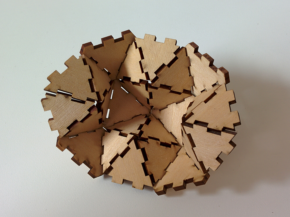
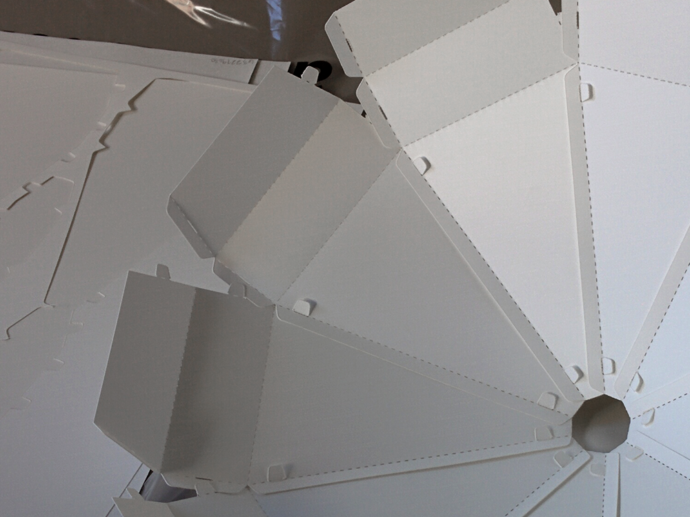
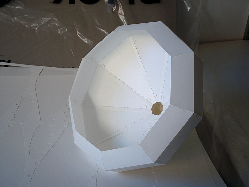
About
Getting Started
Joinery is a web-based tool kit designed to help users generate parametric joints for laser cutting. It takes SVG documents as input, and enables users to define joints by selecting a pair of paths in an SVG. Various joint profiles can be created and applied to the joints—and these can be customized based on material needs and user preferences.
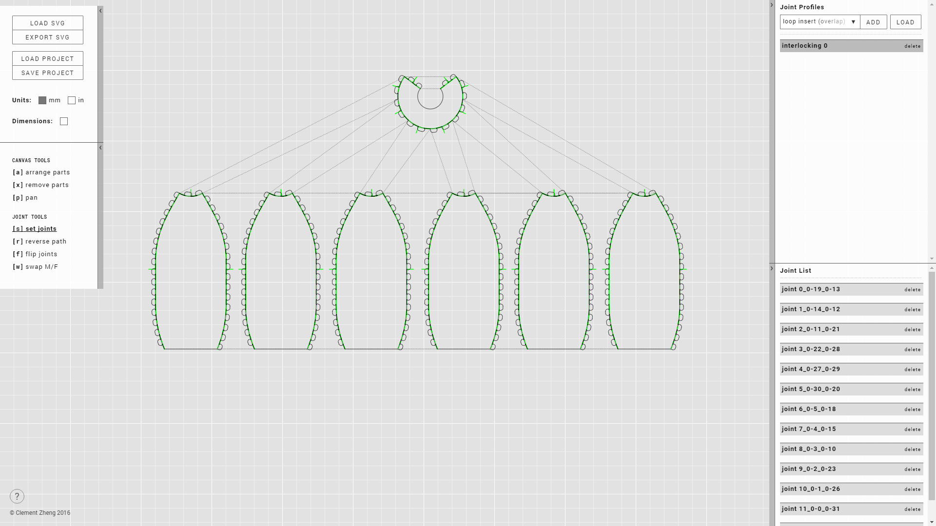 ↑ Interface overview
SVG Preparation
This tool kit generates joints based on SVG files as input. We will use Adobe Illustrator in the following instructions to explain SVG preparation; but, the same should apply for any other vector drawing tool.
-
Break your design down into flat parts, and determine the materials you will use. Draw these 2D parts with a vector drawing tool. Lay them out on the document, ensurng that there is ample space between each part.
Make sure your document's units is set to millimeters or inches!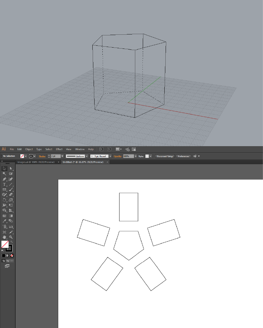
-
Determine which edges you want to join in the laser cut assembly. Separate each individual edge. To elaborate, each different joint edge should be its own path; in Illustrator, a common method is to use the "cut" (scissors) tool to separate paths into different edge segments.
Straight edges should only have two anchor points, defining the start and end of the line. The start and end anchor points should not have any "handles".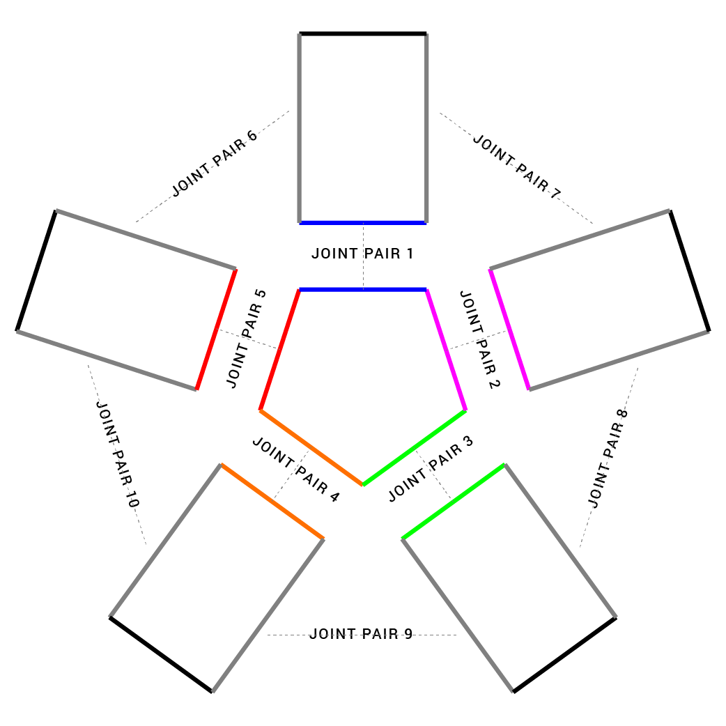
-
Ensure that all joint edges are ungrouped. Other artwork that will not be used for joints can be grouped. Joinery will not be able to edit paths in a group, and you can use this to organize the paths in your file.
Export your file to SVG. Ensure that the SVG is not responsive. If you are using Illustrator, use the "export" function to create the SVG, rather than "save as".
Loading SVGs
-
Open Joinery on a web browser. link
Click on the "Load SVG" button to import an SVG file into the tool kit. Multiple SVG files can be imported into the same workspace.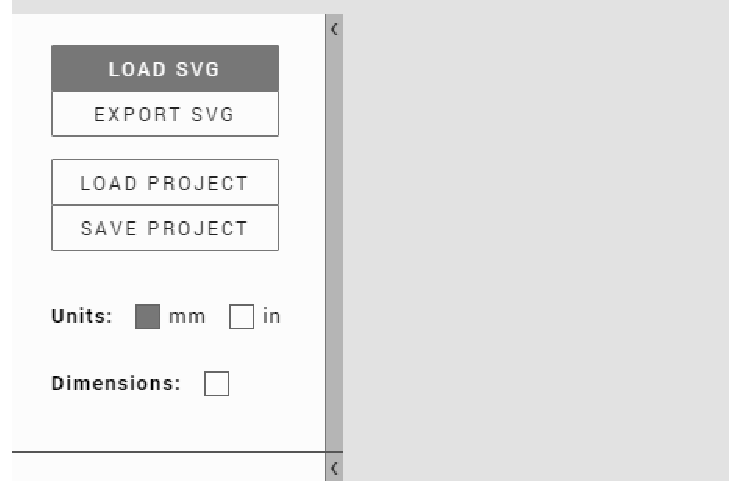
Basic Controls
-
The interface is organized in four main sections.
Left: System controls such as loading and exporting SVG, changing units, dimensions, and control tools.
Right: Joint profile panel and joint list panel.
The workspace occupies the rest of the interface, and this is where imported SVG files are displayed.
-
Holding "space" and dragging with the mouse enables you to pan the workspace. Scrolling with the mouse wheel enables you to zoom in and out of the workspace.
-
"arrange parts": use this tool to move individual SVG files around.
-
"remove parts": use this tool to remove individual SVG files from the workspace.
Defining Joints
-
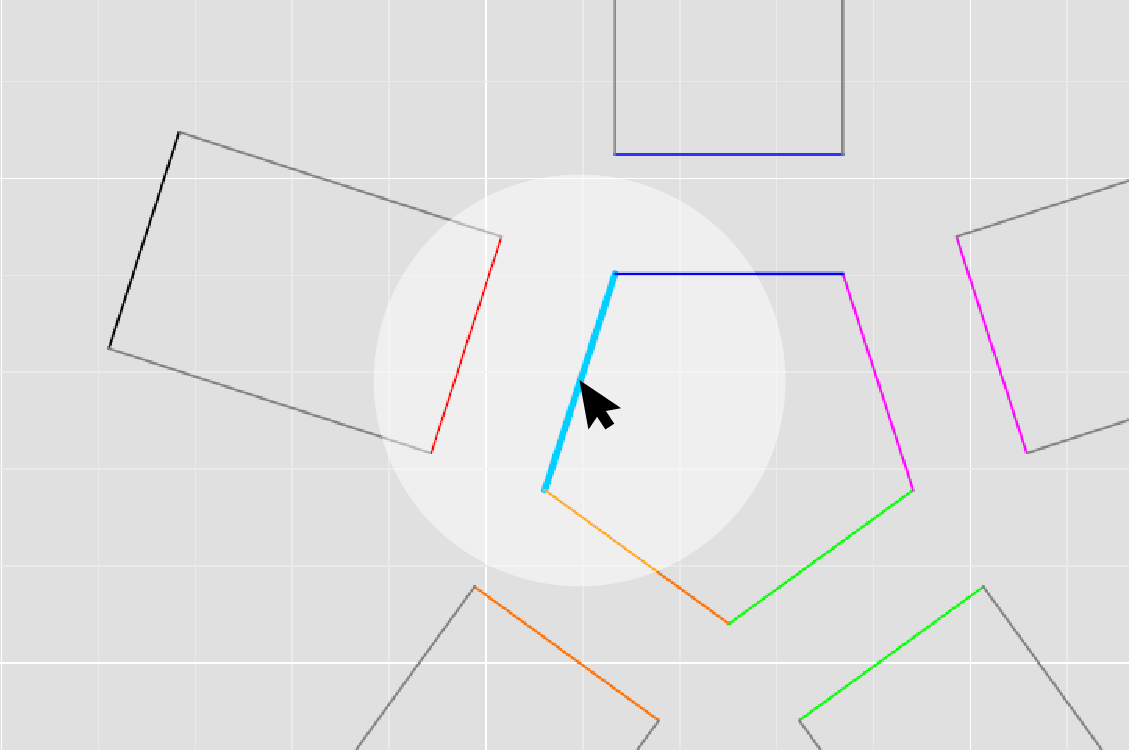
The set joints tool is used to define joints by selecting edge pairs. Hovering over a SVG path with this tool will highlight the path if it is a valid joint path. Click on the path to add it to a joint.
-
A joint is defined once two edges have been selected. Joints will appear in the joint list panel, and will be connected via dashed lines in the workspace.
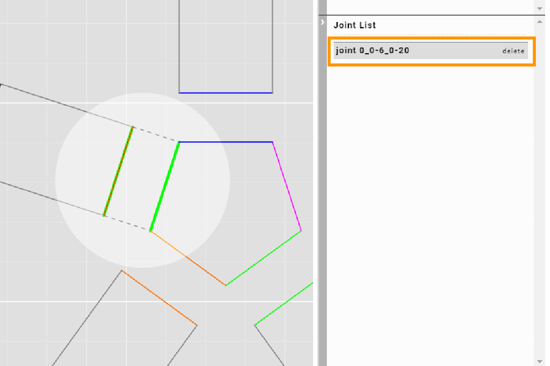
-
If the length of two paths are significantly different, they cannot be paired to form a joint.
Creating Joint Profiles
-
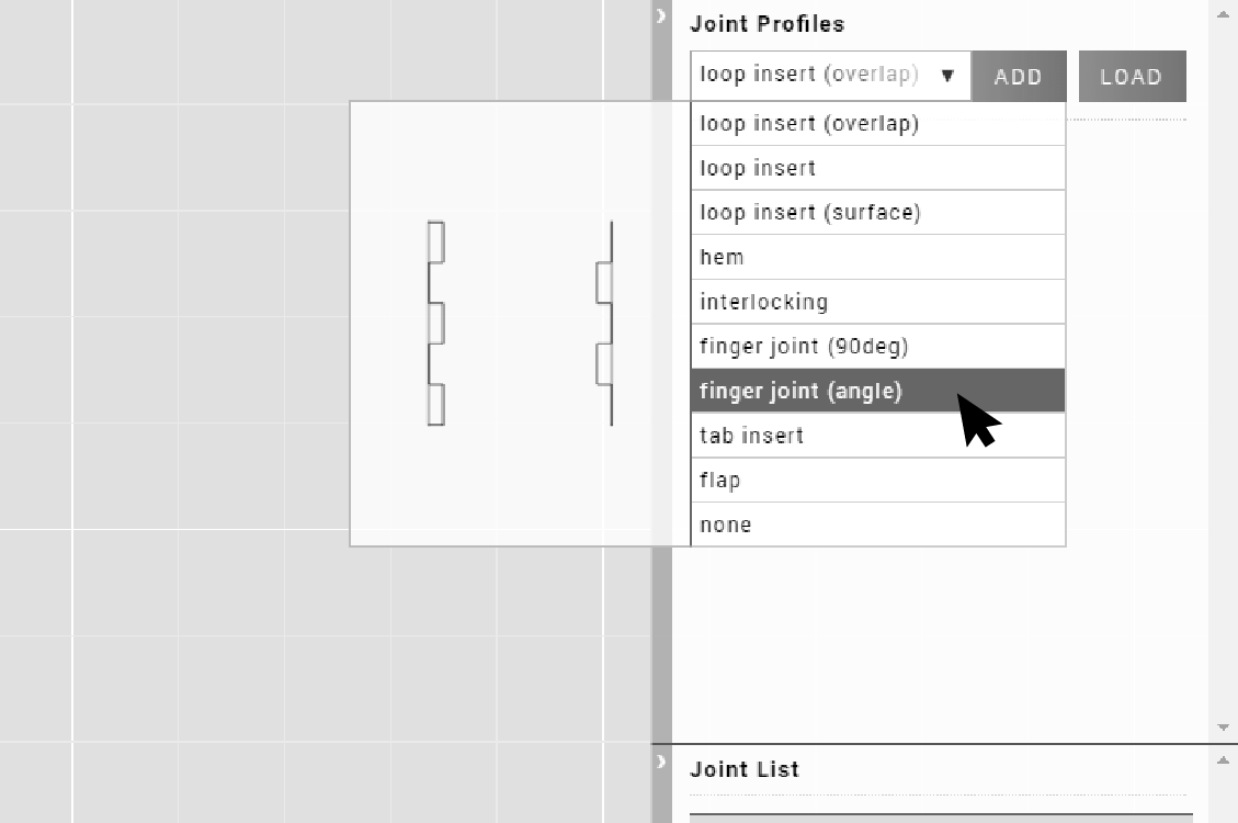
Joinery offers various joint profiles for different purposes. To add a joint profile, click on the joint profile dropdown menu. As you hover over the different joint profiles, a thumbnail will appear showing an example of that profile.
-
Click to select a joint profile from the dropdown menu, and click "add" to create a joint profile.
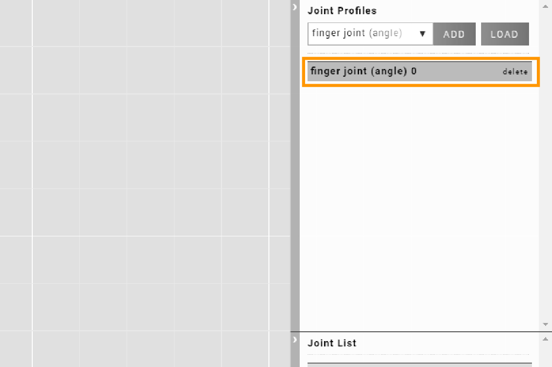
-
Click on a joint profile to expand it. This displays the different parameters and options for customizing the joint profile.
The notes text box allows you to jot down notes for later reference. This can include material or design details.
Joint parameter values can be modified by typing new values for the different parameters.
"set joint" saves the notes and parameters and applies any changes.
"save profile" exports the current joint profile. Exported joint profiles can be loaded via the "load" button in the joint profile panel. Use this to save profiles for future use, or to share them with others.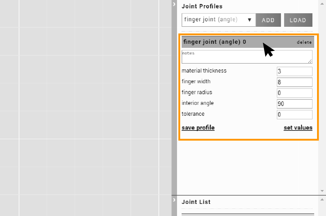
Modifying Joints
-
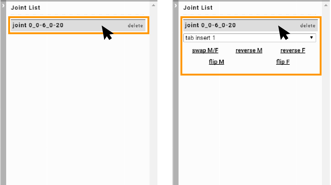
Selecting a joint in the joint list panel expands it. Select a joint profile from the dropdown menu to apply that joint profile to the joint. The same joint profile can be applied to multiple joints. Modifying the parameters of a joint profile will therefore modify all the joints it is applied to.
-
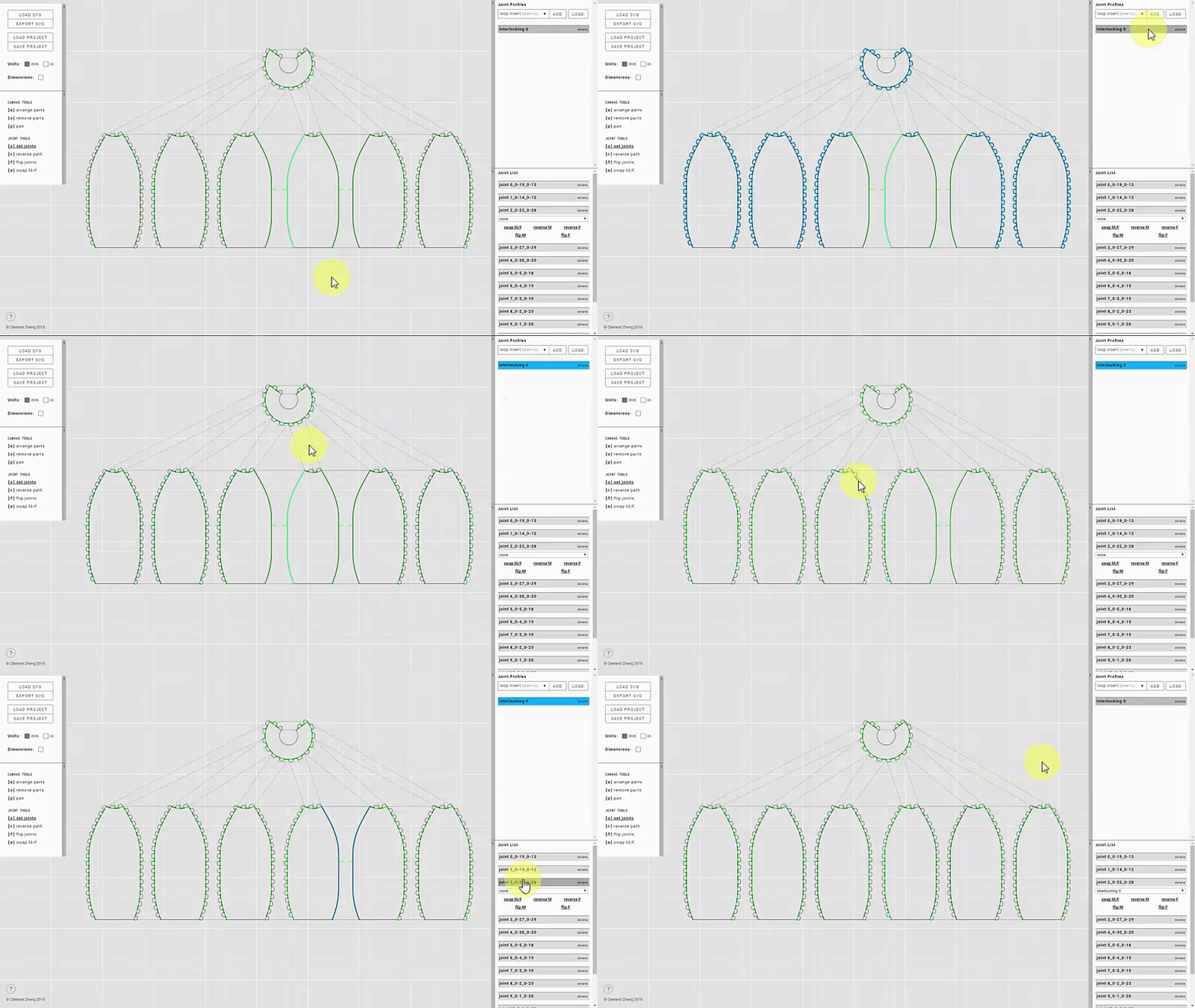
You can also apply joint profiles to joints by shift-clicking on a joint profile. The joint profile to be applied will be highlighted in blue. While holding on to shift, you can click on joints in the joint list panel to apply that joint profile. Alternatively, while you are in "set joints" mode, you can click on the joint edge itself on the canvas to apply that joint profile.
-
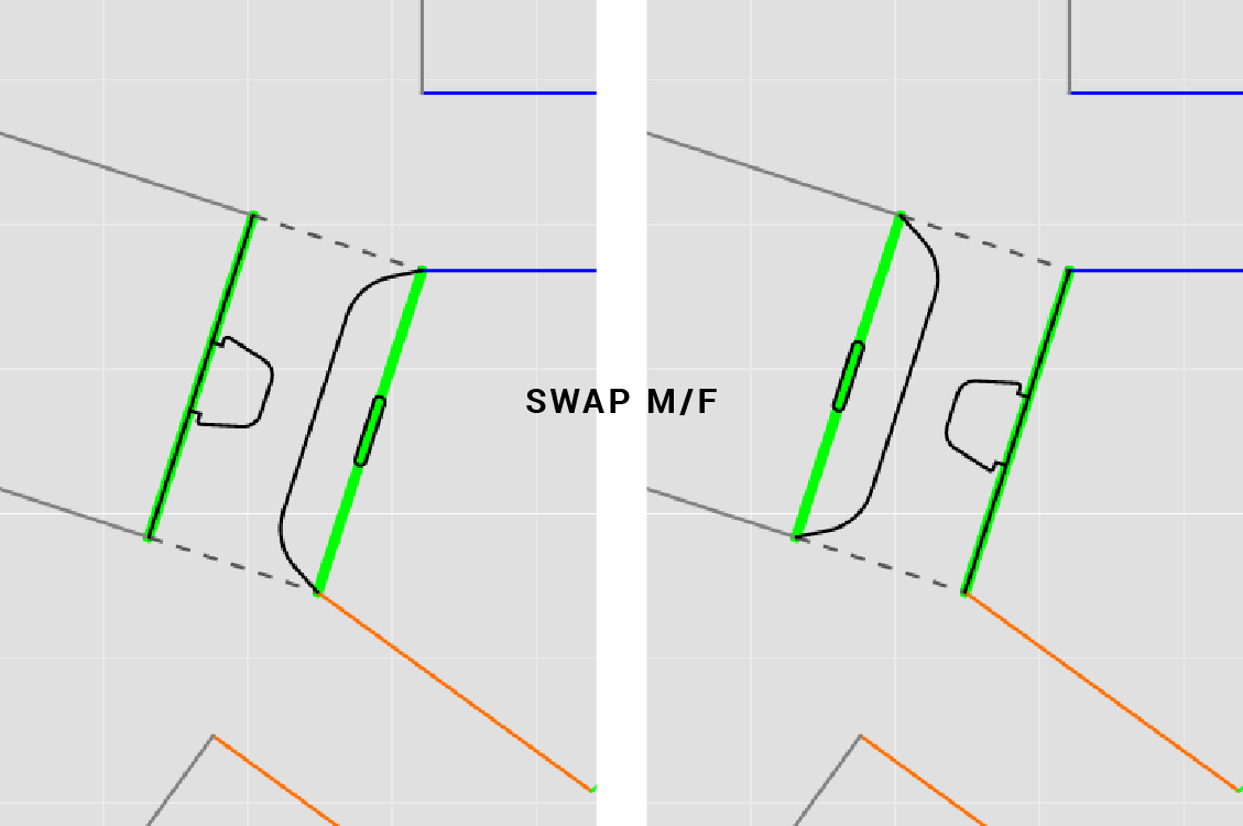
"swap M/F" swaps male and female joints.
-
"reverse M" reverses the direction of the male joint.
"reverse F" reverses the direction of the female joint.
You should see the dashed lines connecting the two edges of a joint flip after reversing. You can also use the "reverse path" tool and click on the path you would like to reverse.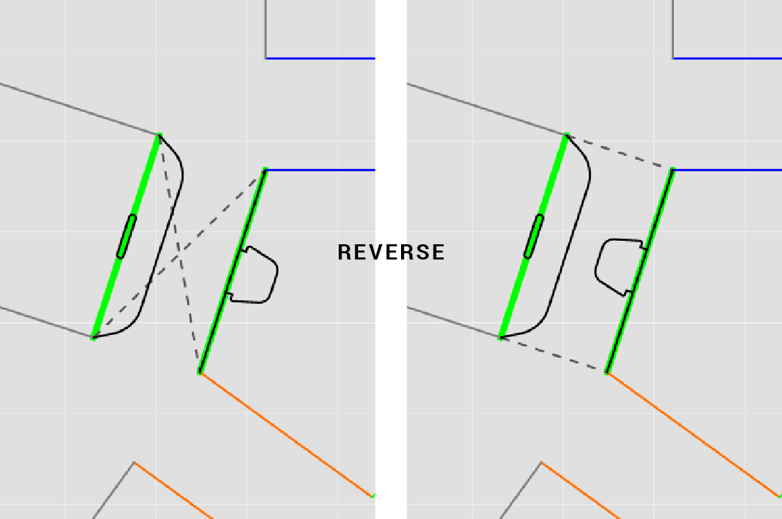
-
"flip M" flips the normal direction of the male joint.
"flip F" flips the normal direction of the female joint.
You should see the joint extending in the opposite direction (normal to the path) after flipping. You can also use the "flip joints" tool and click on the path you would like to flip.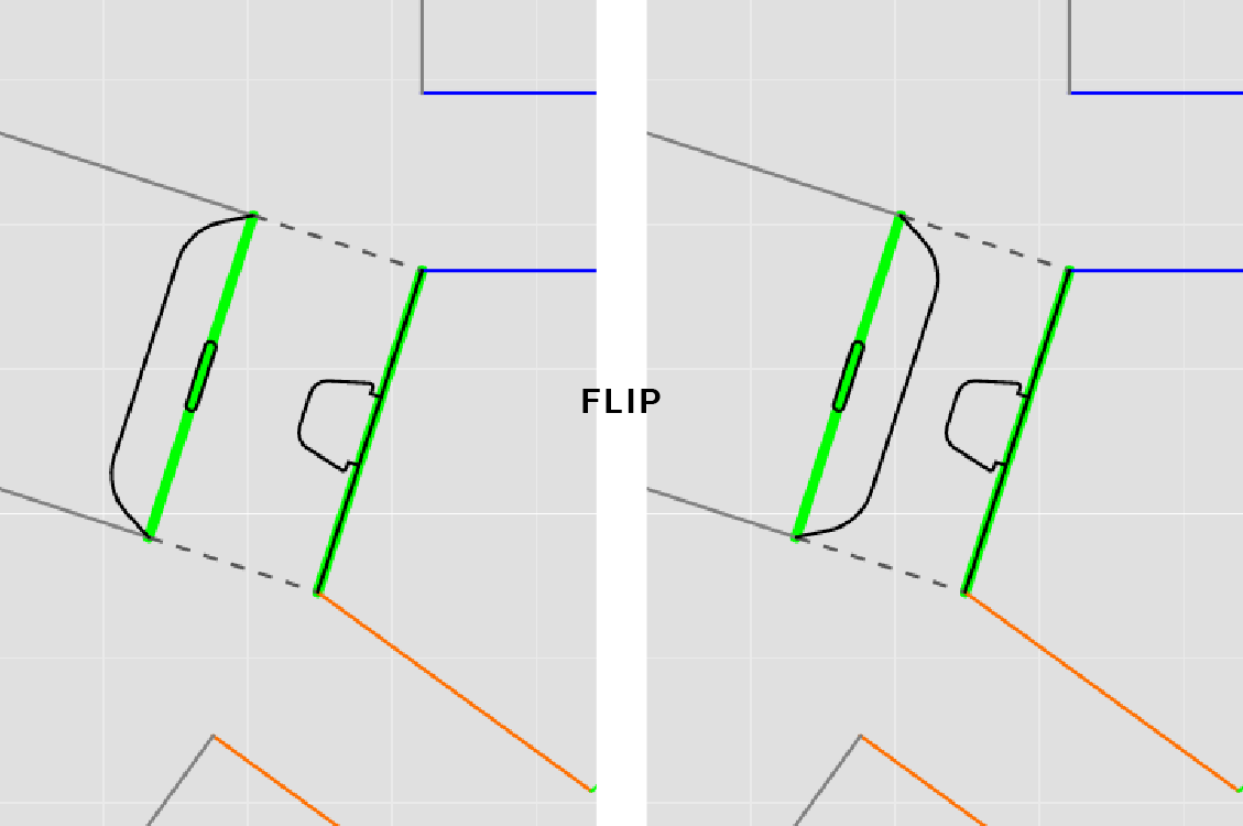
Exporting SVG
-
You can export your design, along with the generated joints, as an SVG file. This file can be used an input for laser cutting, or for further design work if necessary.
-
Paths are color coded in the exported file. These colors will be useful for organizing the different paths during the fabrication process.
Blue paths are joint paths generated by Joinery.
Aqua paths are fold paths generated by Joinery.
Red paths are the orginal paths.
Purple paths are grouped paths.
Save and Load Projects
-
You can save your work in Joinery. Clicking on "save project" will export a .joinery file, which you can access another time through "load project".
Joint Profiles
Joinery offers various joint profiles for connecting and assembling flat parts together. Different joint profiles cater to different materials and purposes. This section elaborates on the use of each joint profile, and explains the customizable parameters within each profile.
Loop Insert (Overlap)
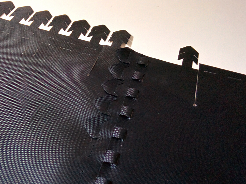
Loop Inserts are designed to interface fabrics with fabrics, or fabrics with stiff materials. They can be used as a replacement for conventional sewing or other fasteners. Loop Insert (Overlap) extends the edge of the joint, creating an overlapping region between the two parts.
Note
Male joints should be generated on fabric/soft materials.
Works on both curve and straight paths.
Parameters
Material Thickness M
Thickness of the material with the male joint.
Material Thickness F
Thickness of the material with the female joint.
Hem Offset
Width of overlap; offset distance from the orginal edge.
Insert Width
Width of the insert's stem.
Hook Width
Width of the hooks that extend from the insert's stem.
Joint Spacing
Space between each insert.
Slack
The amount of slack between the insert and the slits.
0: no slack
0<: looser inserts with specified amount of slack
0>: tighter inserts where inserts are shorter than loop space.
Offset Start
Distance from start where joints begin.
Offset End
Distance from end where joints end.
Loop Insert
Loop Inserts are designed to interface fabrics with fabrics, or fabrics with stiff materials. They can be used as a replacement for conventional sewing or other fasteners. This Loop Insert variation does not extend the edge of the female joint; that is, there will not be overlap between the two parts.
Note
Male joints should be generated on fabric/soft materials.
Works on both curve and straight paths.
Parameters
Material Thickness M
Thickness of the material with the male joint.
Material Thickness F
Thickness of the material with the female joint.
Hem Offset
Width of overlap; offset distance from the orginal edge.
Insert Width
Width of the insert's stem.
Hook Width
Width of the hooks that extend from the insert's stem.
Joint Spacing
Space between each insert.
Slack
The amount of slack between the insert and the slits.
0: no slack
0<: looser inserts with specified amount of slack
0>: tighter inserts where inserts are shorter than loop space.
Offset Start
Distance from start where joints begin.
Offset End
Distance from end where joints end.
Loop Insert (Surface)
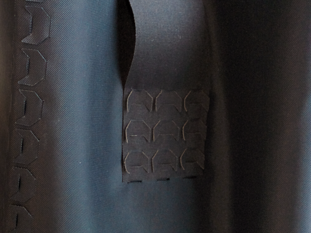
Loop Inserts are designed to interface fabrics with fabrics, or fabrics with stiff materials. They can be used as a replacement for conventional sewing or other fasteners. This Loop Insert variation connects two surfaces together
Note
Male joints should be generated on fabric/soft materials.
Works on straight paths only.
Parameters
Material Thickness M
Thickness of the material with the male joint.
Material Thickness F
Thickness of the material with the female joint.
Hem Offset
Width of overlap; offset distance from the orginal edge.
Insert Width
Width of the insert's stem.
Hook Width
Width of the hooks that extend from the insert's stem.
Hook Count
Number of hooks.
Joint Spacing
Space between each insert.
Slack
The amount of slack between the insert and the slits.
0: no slack
0<: looser inserts with specified amount of slack
0>: tighter inserts where inserts are shorter than loop space.
Offset Start
Distance from start where joints begin.
Offset End
Distance from end where joints end.
Hem
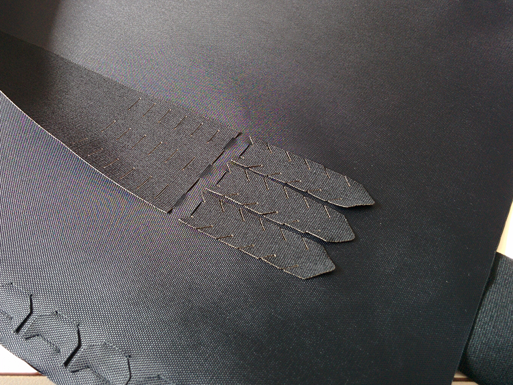
This joint extends the edge by a specified amount. If required, it can also generate holes along the original edge to guide sewing.
Note
Works on curve and straight paths.
Parameters
Hem Offset
Width of overlap; offset distance from the orginal edge.
Hole Diameter
Size of hole. Holes will not be generated if 0 is specified.
Hole Spacing
Space between holes.
Interlocking
A series of alternating tabs that interlock along the joint edge. This joint works well on flexible paper-based or plastic materials.
Note
Works on curve and straight paths.
Parameters
Material Thickness M
Thickness of the material with the male joint.
Material Thickness F
Thickness of the material with the female joint.
Interlocking Width
Width of the interlocking tab's stem.
Interlocking Height
Height of each interlocking tab.
Offset Start
Distance from start where joints begin.
Offset End
Distance from end where joints end.
Grip
Amount of overlap between interlocking tabs.
Finger Joint (90deg)
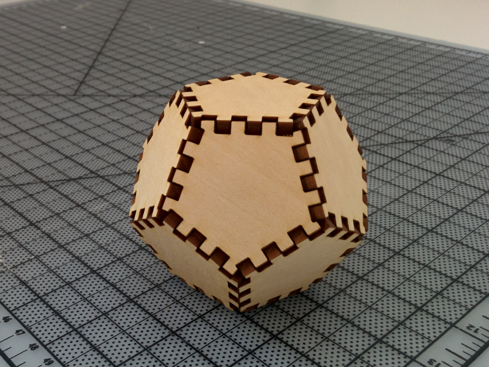
A series of alternating protrusions that interlocking two parts at a right angle. The is a common joint used to fabricate boxes from thicker sheet materials like acrylic and bass wood. Adhesives like hot/super glue can be used to reinforce this joint and create a permanent connection.
Note
Works on straight paths only.
Parameters
Material Thickness M
Thickness of the material with the male joint.
Material Thickness F
Thickness of the material with the female joint.
Finger Width
Width of the interlocking finger.
Finger Radius
Outer corner radius of the interlocking finger. Rounding the corners of the interlocking fingers can help ease two parts together to form the joint.
Offset Start
Distance from start where joints begin.
Offset End
Distance from end where joints end.
Tolerance
Amount of overlap between interlocking fingers. Negative tolerance creates interfering finger joints which can be forced fit together for tighter joints.
Finger Joint (angle)
A series of alternating protrusions that interlocking two parts at a specified interior angle. This joint is restricted to joining parts with the same thickness, but it enables these parts to be interfaced at angles other than 90 degrees. The interior angle is the dihedral angle between two parts; that is, the plane-to-plane angle.
Note
Works on straight paths only.
Parameters
Material Thickness M
Thickness of the material with the male joint.
Material Thickness F
Thickness of the material with the female joint.
Insert Width
Width of the interlocking finger.
Finger Radius
Outer corner radius of the interlocking finger. Rounding the corners of the interlocking fingers can help ease two parts together to form the joint.
Offset Start
Distance from start where joints begin.
Offset End
Distance from end where joints end.
Tolerance
Amount of overlap between interlocking fingers. Negative tolerance creates interfering finger joints which can be forced fit together for tighter joints.
Tab Insert
This joint generates a series of tabs which insert into corresponding slits on a flap. It is commonly used on paper-based materials for quick assembly. Do note that you may need to create folding lines for the tabs and flaps for stiffer materials; for example, a perforated line to make folding easier after fabrication.
Note
Works on straight paths only.
Parameters
Material Thickness M
Thickness of the material with the male joint.
Material Thickness F
Thickness of the material with the female joint.
Insert Width
Width of the insert's stem.
Insert Height
Height of the insert.
Flap Height
Height of the flap.
Joint Spacing
Space between each insert.
Offset Start
Distance from start where joints begin.
Offset End
Distance from end where joints end.
Grip
Amount of overlap between interlocking tabs.
Flap
This joint generates a flaps on either side of the joint, which can then be connected with adhesives such as hot glue or double sided tape.
Note
Works on straight paths only.
Parameters
Height M
Male flap height.
Height F
Female flap height.

